Network maps for projects
Permissions and access
Minimum role: Researcher
In the CoBaseKRM web client, a network map is a visual framework for organizing data files and metadata by project activities and tasks.
You can create multiple network maps for a project. You can also create subprojects to represent meaningful groups of activities within a project.
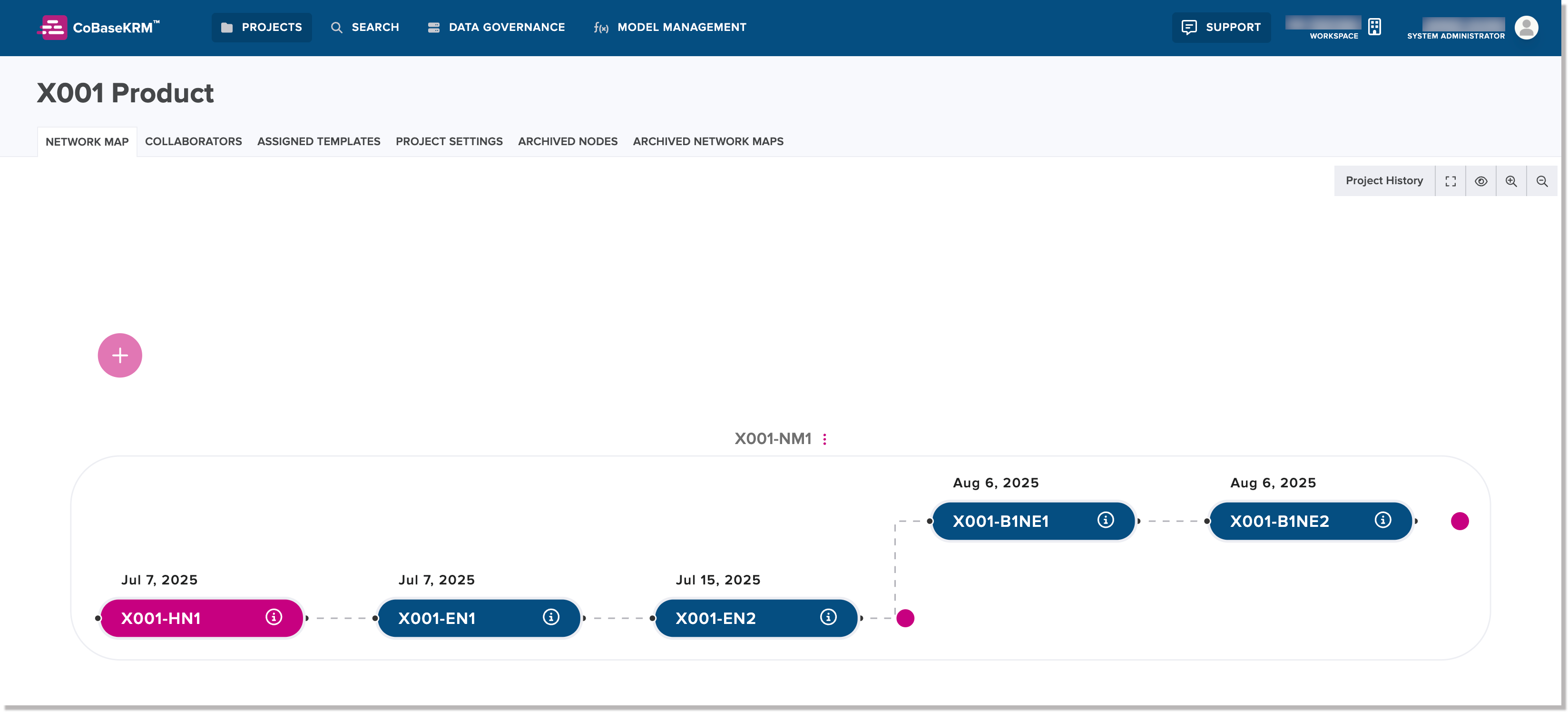
Network Map view for a project
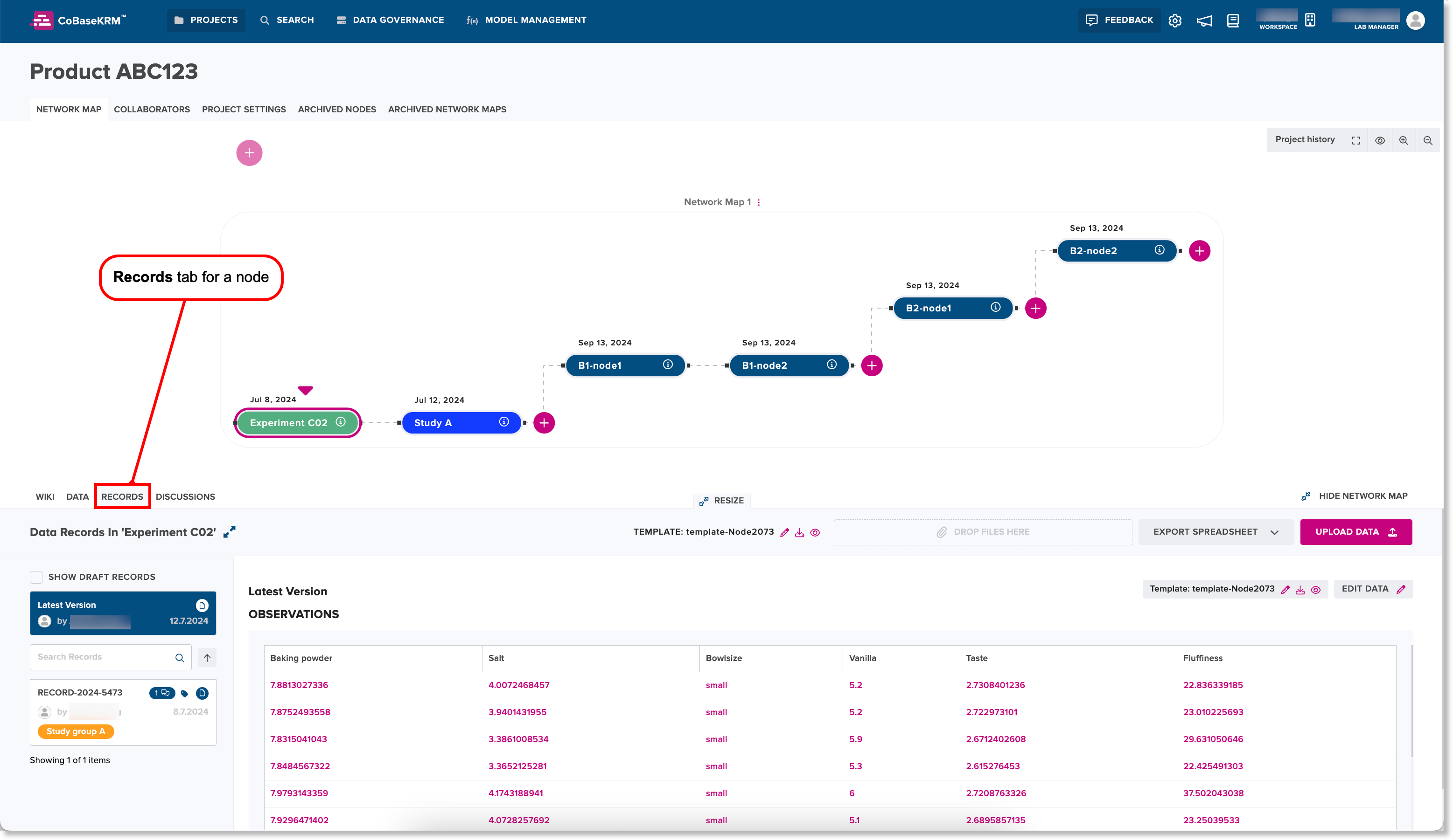
When you navigate into a project from the Projects view, the Network Map tab is displayed by default. The Network Map tab displays one or more network maps for classifying and structuring project activities visually. The following screenshot shows the various components within the Network Map tab for a project.
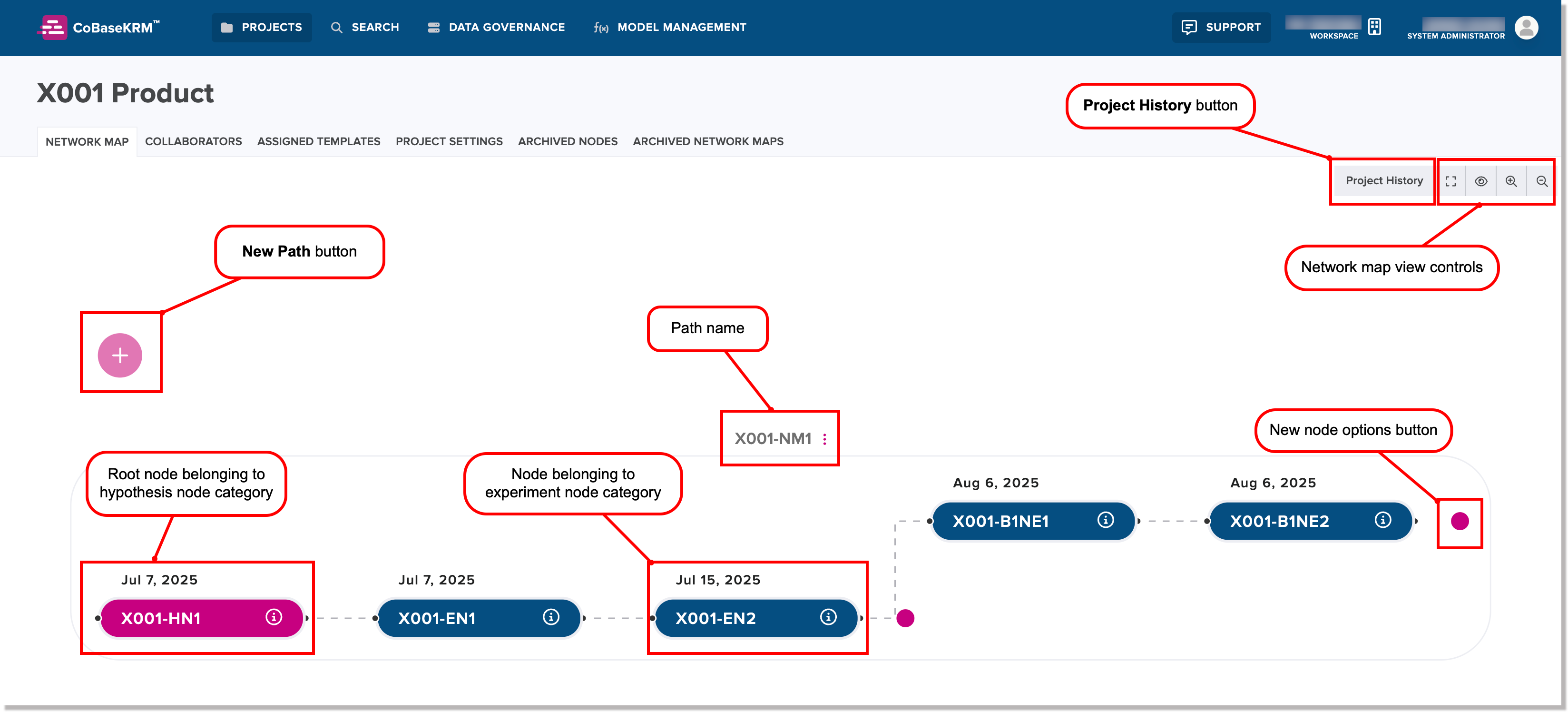
A network map is structured by the following key objects:
-
Nodes are objects that represent individual project activities, such as a research experiment that follows a prescribed set of process parameters. Data belonging to a single node is organized into records, which are saved when files are uploaded to the database. Other metadata and relevant details in relation to nodes are also saved. The following node types are supported:
-
A branch node represents a level within the data hierarchy of a network map. The main branch node at the top level of a network map is created when a network map is created. You can create other branch nodes at other levels of a network map.
-
A leaf node represents a child node that is created from a parent node within the same branch or level of the network map hierarchy.
Each node within a network map has only one set of managed observations and parameters. A node can contain any number of supplementary files, which are not version controlled. But data sets that are structurally different or ones that should be maintained separately for any logical reason should be associated to their own separate nodes, if they are being uploaded as managed observations.
-
-
Node categories are general categories for grouping nodes by a particular process or type of experiment. Each node category is defined with a hex color code to visually differentiate nodes that belong to it. The predefined node categories are:
- Hypothesis - denotes a project activity that is related to a hypothesis and may be the root node of a given path of a network map
- Experiment - denotes a project activity that is an experiment or scientific investigation using a prescribed method and may involve testing and data collection
- Conclusion - denotes a project activity that involves reviewing, analyzing, and summarizing performance results and decision making for continuing with next phases of a project or concluding a project
-
Connectors are connecting lines to show existing relationships between nodes.
View control icons for network maps
The following view control icon buttons are used to help you view the details of network maps. They are positioned at the top right within the Network Map tab for a project.
| Icon | Tooltip | Description |
|---|---|---|
| Full screen view | Expands the view of the Network Map tab to fullscreen to fill the tab of the browser window | |
| Normal screen view | Displays the normal view of the Network Map tab within the tab of the browser window | |
| Restores default view | Restores the default view dimensions of the Network Map tab | |
| Zoom in | Zooms in the dislay to show a closer view of the Network Map tab | |
| Zoom in | Zooms ou the dislay to show a broader view of the Network Map tab |
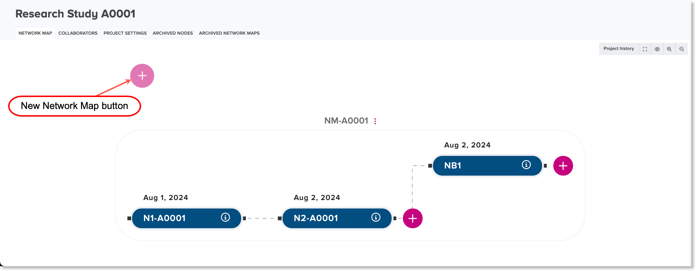
Create a network map and its root node
When you create a new project, the Network Map tab view is empty by default. Use the Create First Network Map button to create a first network map and its root node. If you want to create additional network maps, use the New Network Map (plus symbol) button.
To create a network map and its root node for a project:
-
Create either of the following:
-
a first network map for a new project by clicking or tapping the Create First Network Map button

-
an additional network map to one or more existing network maps by clicking or tapping the New Network Map (plus symbol) button
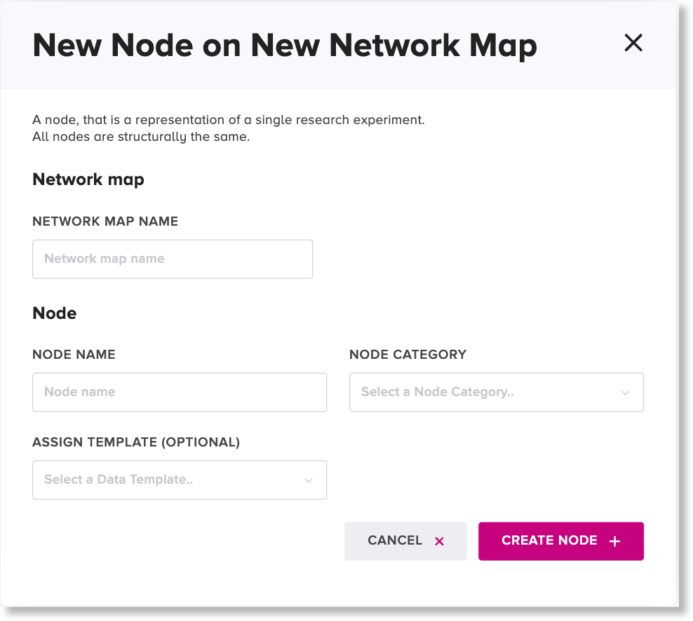
The New Node on Network Map dialog appears.
-
-
In the Network Map Name field, type a name for the new network map.
-
In the Node Name field, type a name for the root node of the new network map.
-
In the Node Category field, select a node category that you want the root node to belong to.
Note
The Template field for the root node is automatically assigned the name of the default template assigned to the given project.
-
Optional: To assign a different template to the root node, other than the project-assigned template, for parameter matching, click or tap the Assign Template field and either select an existing template or create a new template.
-
Click the Create Node button.
The new network map and its root node are displayed in the Network Map view.
Create a node within a branch
To create a node within a branch:
-
Click or tap the new node button (add symbol with a circle around it) to the right of an existing node where you want to position a new node in a branch. From the menu, select the New node option.
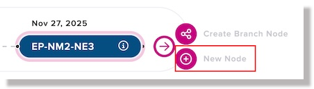
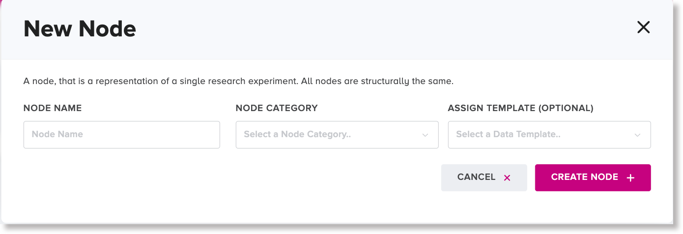
The New Node dialog appears.
-
In the Node Name field, type a name for the new node.
-
In the Node Category field, select a node category that you want the new node to belong to.
-
Optional: To assign a template to the node, select one of the following options:
-
To assign a project template to the new node, click or tap the Assign Template field and select a template name from the list.
-
To assign the same template that has been assigned to the preceding node, select the Copy the Template from the Parent Node checkbox.
-
-
Click or tap the Create Node button.
The new node is created to the right of the preceding node of the same branch.
Create a branch node
A branch node is the first node of a new branch that stems from from an existing branch of a network map.
To create a branch node:
-
Click or tap the add button to the right of an existing node in a branch, where you would like the new branch node to be positioned. From the menu, select the New branch node option.
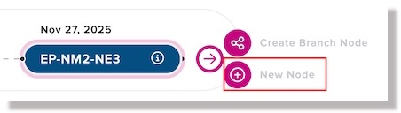
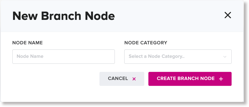
The New branch node dialog appears.
-
In the Node Name field, type a name for the new node.
-
In the Node Category field, select a node category that you want the new node to belong to.
Note
The system turns on the Copy template from parent node checkbox and display a template preview by default to enable the new branch node to inherit the same template as the preceding node, but you have the option to assigning a different template.
-
Optional: To select and assign a different template to the new branch node, turn off the Copy template from parent node checkbox and click the Assign Template field to select a different template name or create a template.
-
Click or tap Create Branch Node button.
The new branch node appears in the related network map, stemming from an existing branch.
Create a new template for a node
This task is optional and is part of step 4 of the create a new node within a branch workflow and the create a new branch node workflow.
To create a template for a node:
-
If the Copy template from parent node checkbox is turned on, click to turn it off.
-
Click or tap the Assign Template field and from the drop-down list, select the Create Template option.
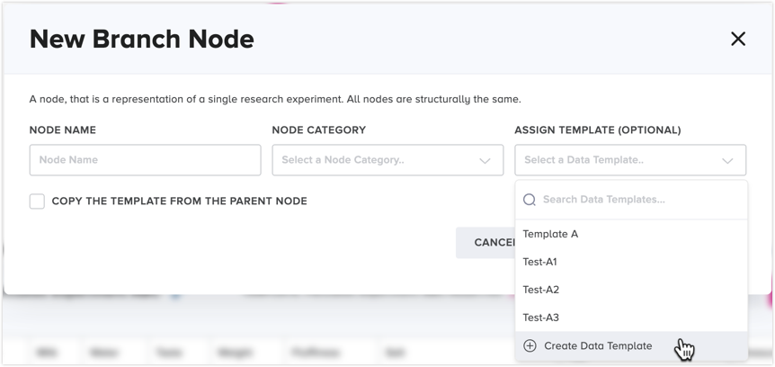
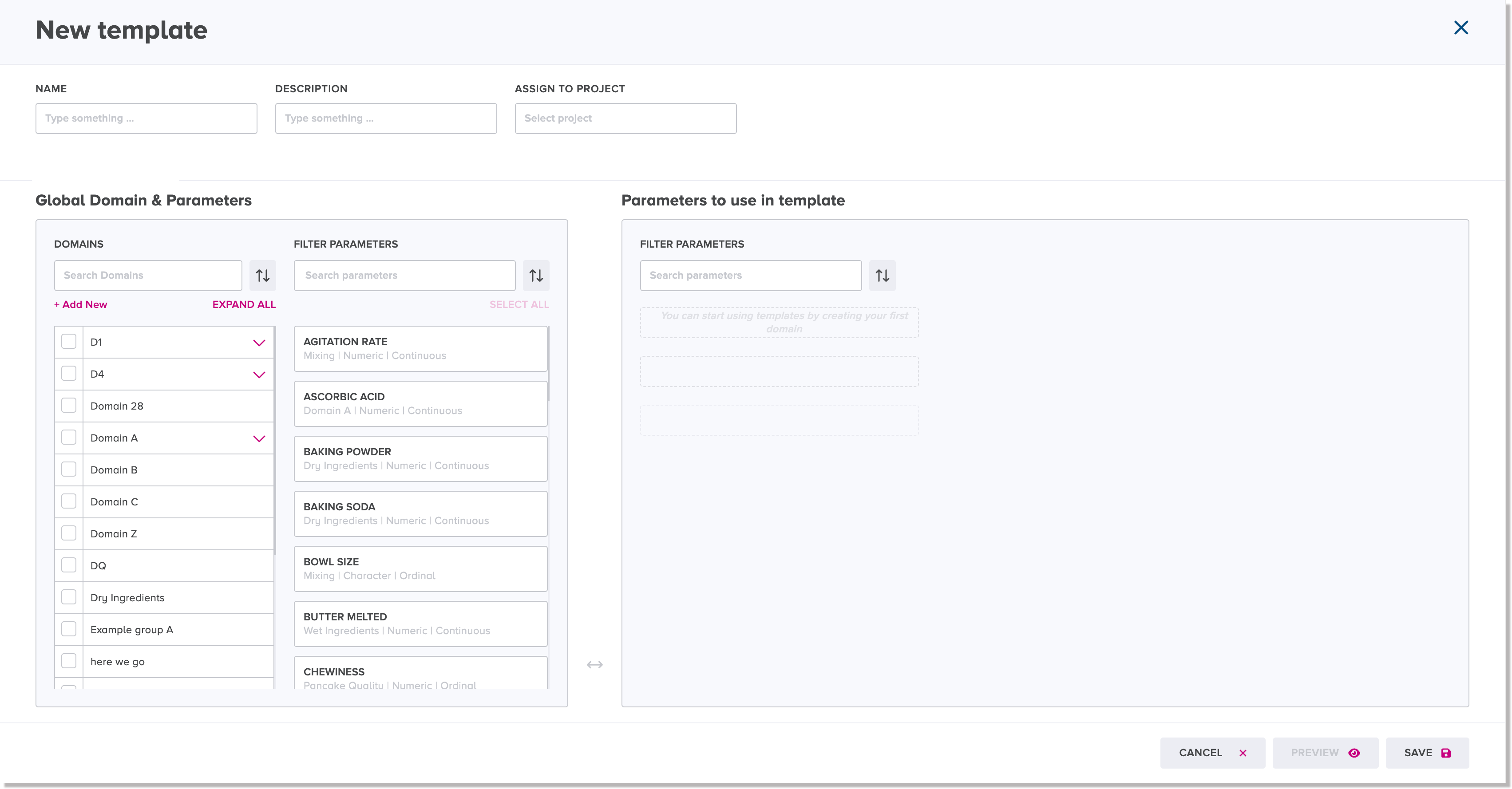
The New Template dialog appears.
-
In the Template Name field, type the name that you want to assign to the new template.
-
Optional: If you want to define a description for the new template, type it in the Description field.
-
In the list of parameters, select the checkboxes of the parameters that you want to add to the new template.
The selected parameters are displayed on the left side in the Parameters to use in template section.
Note
If you want to preview the selected parameters in the new template, click or tap the Preview Template button to display the Template Preview window. To close the Template Preview window, click or tap Close Preview.
-
In the New Template dialog, click or tap Save Template.
The New Template dialog disappears, and the new template name is listed in the Assign Template field of the New Node dialog or New Branch Node dialog.
Data tab for a node
The Data tab lists records of all of the existing observations in read-only format in a data table related to a node.
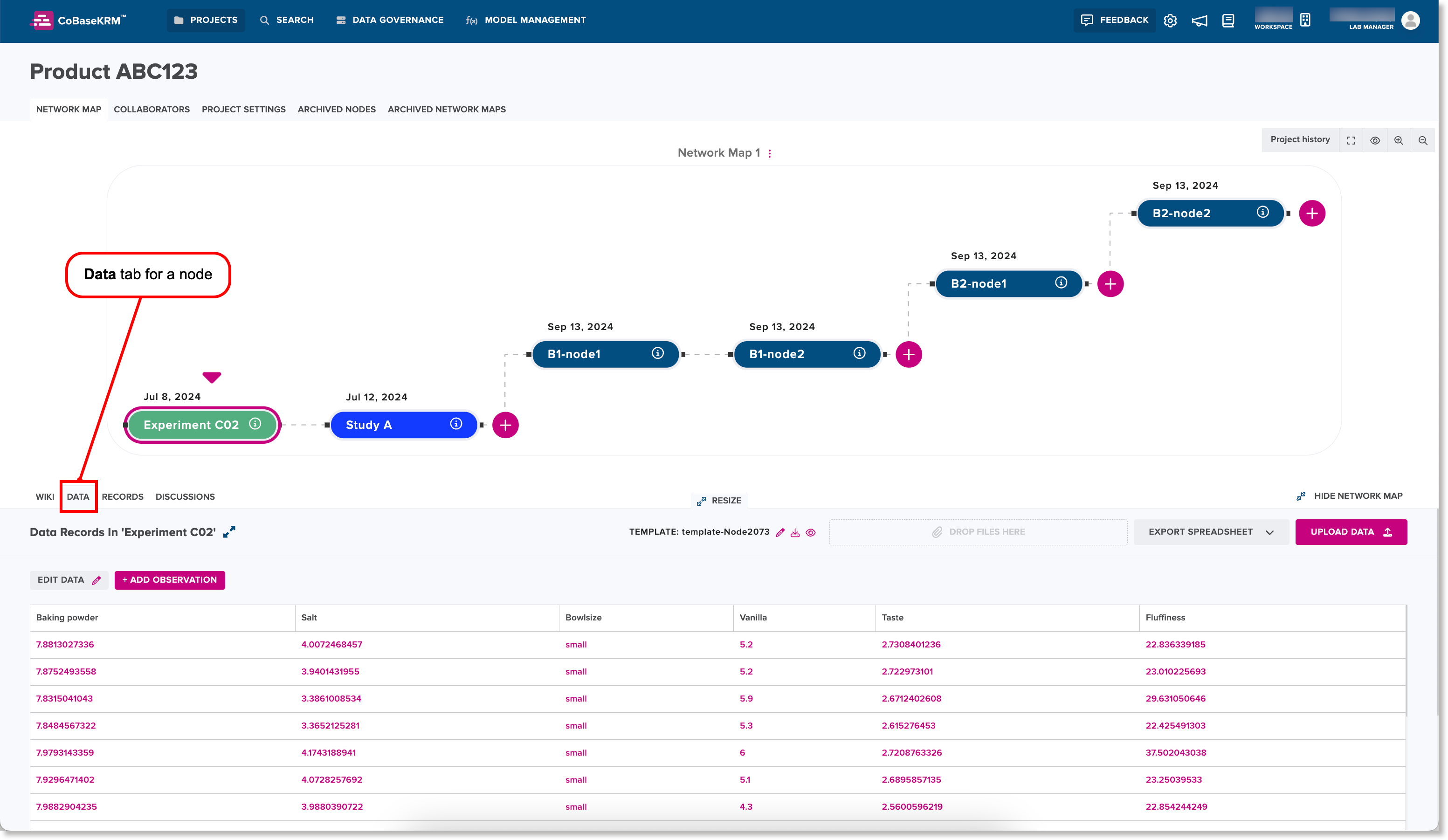
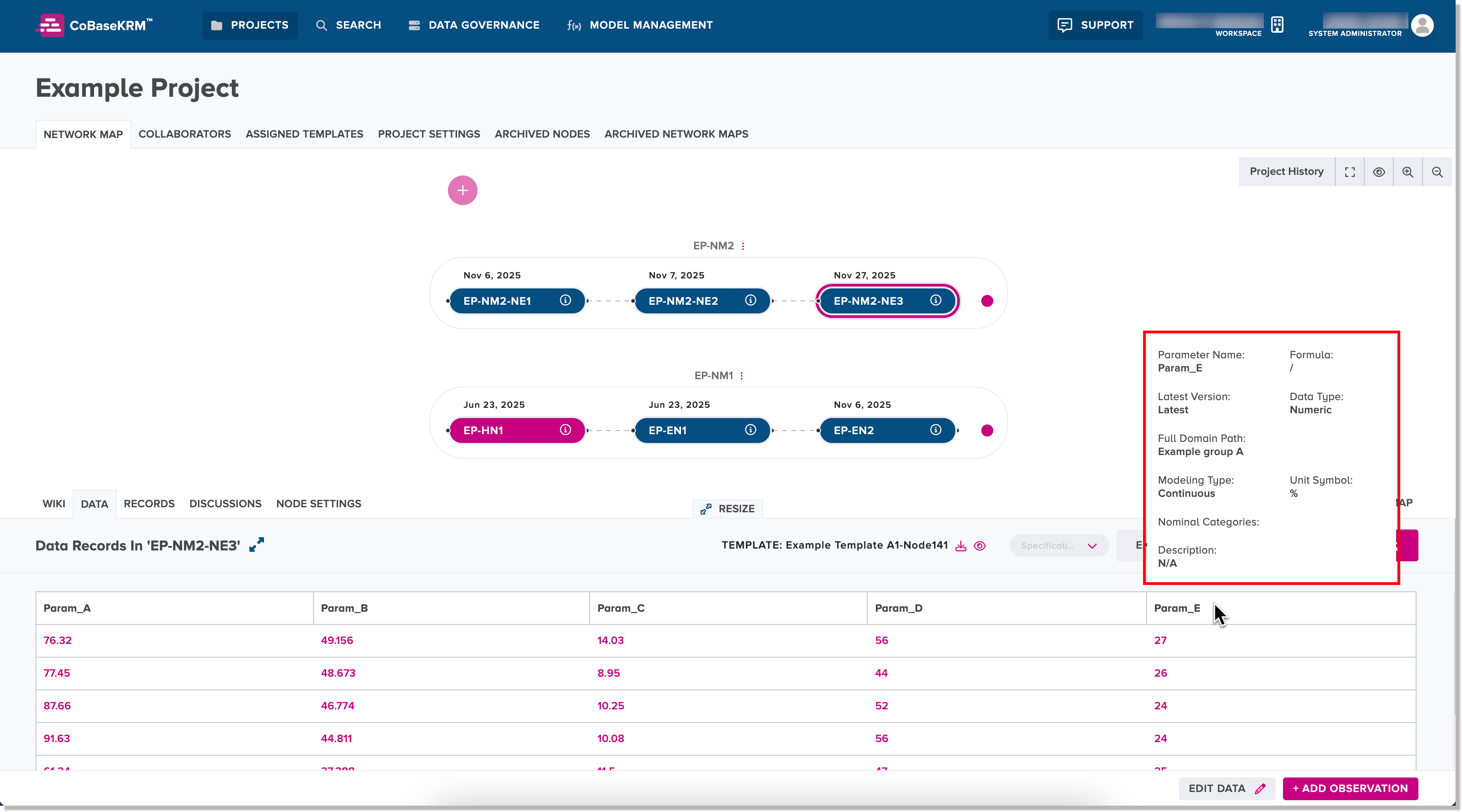
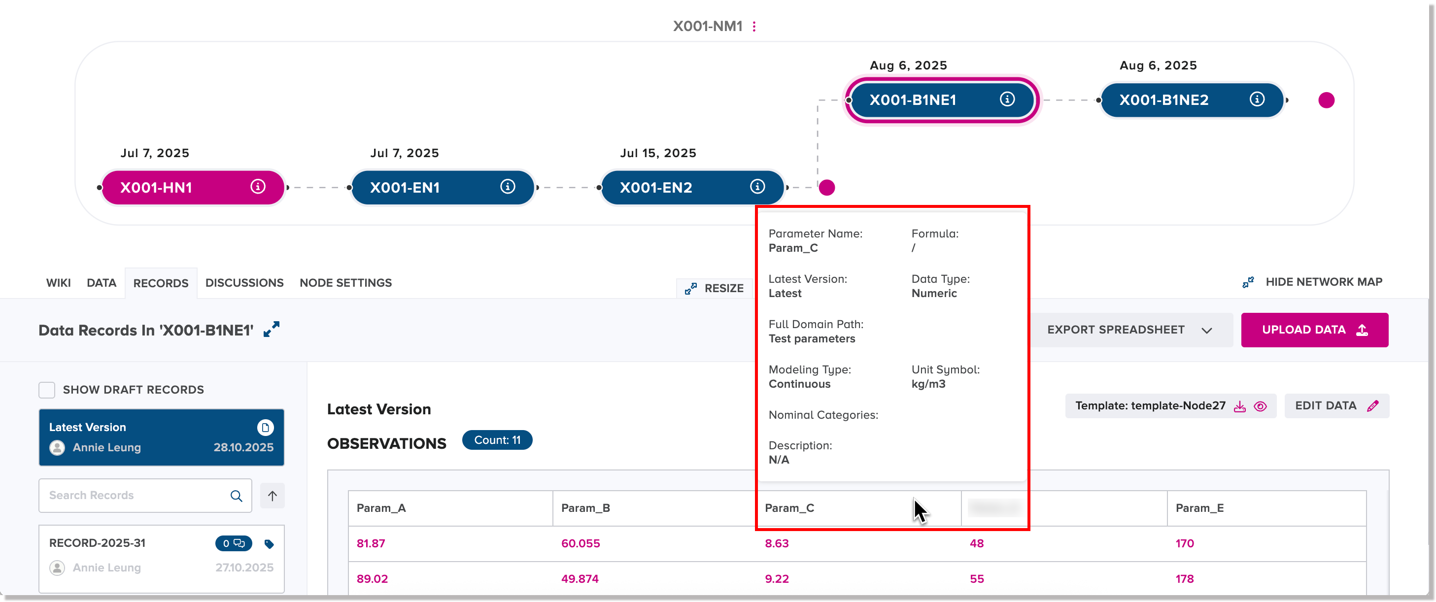
When you hover your cursor over a column heading for a parameter in the data table on the Data tab, a tooltip appears, showing more details and metadata about the parameter.
The main features on the Data tab for a node are:
-
Upload data tables and supplementary files to the given node
-
Export a spreadsheet of existing observations related to the given node
View record details for a parameter value in an observation
If you want to view record details for a parameter value in an observation, click or tap the cell containing a parameter value on the Data tab for a node.
The Data Point right panel appears, listing the following details for the parameter value:
-
Source field - the record ID assigned when the observation was uploaded to the database
-
Project field - the related project name
-
Node field - the related node name
-
Value field - the parameter value
-
Date of Origin field - the date on which the observation was uploaded to the database
-
Author field - the username of the user who uploaded the observation
-
Upload Method field - the method by which the observation was uploaded
Also supported in the right panel are the following functions:
-
Download Modfied File - download the latest version of the modified file in CSV file format containing the observation data point value
-
Download Original File - download the original file in CSV format containing the observation data point value
-
Go to Record button - navigate to the Records tab for the same node so that you can view the corresponding record containing the observation data point value
Compare observation values of parameters related to a node with sets of specification limits
On the Data tab for a node of a network map, you can select one or more specification sets to show a visual representation of how observation values for parameters having a numeric data type fall within or outside acceptable specification ranges.
The Data tab features a drop-down list field containing existing specification sets that you can select for a comparison.
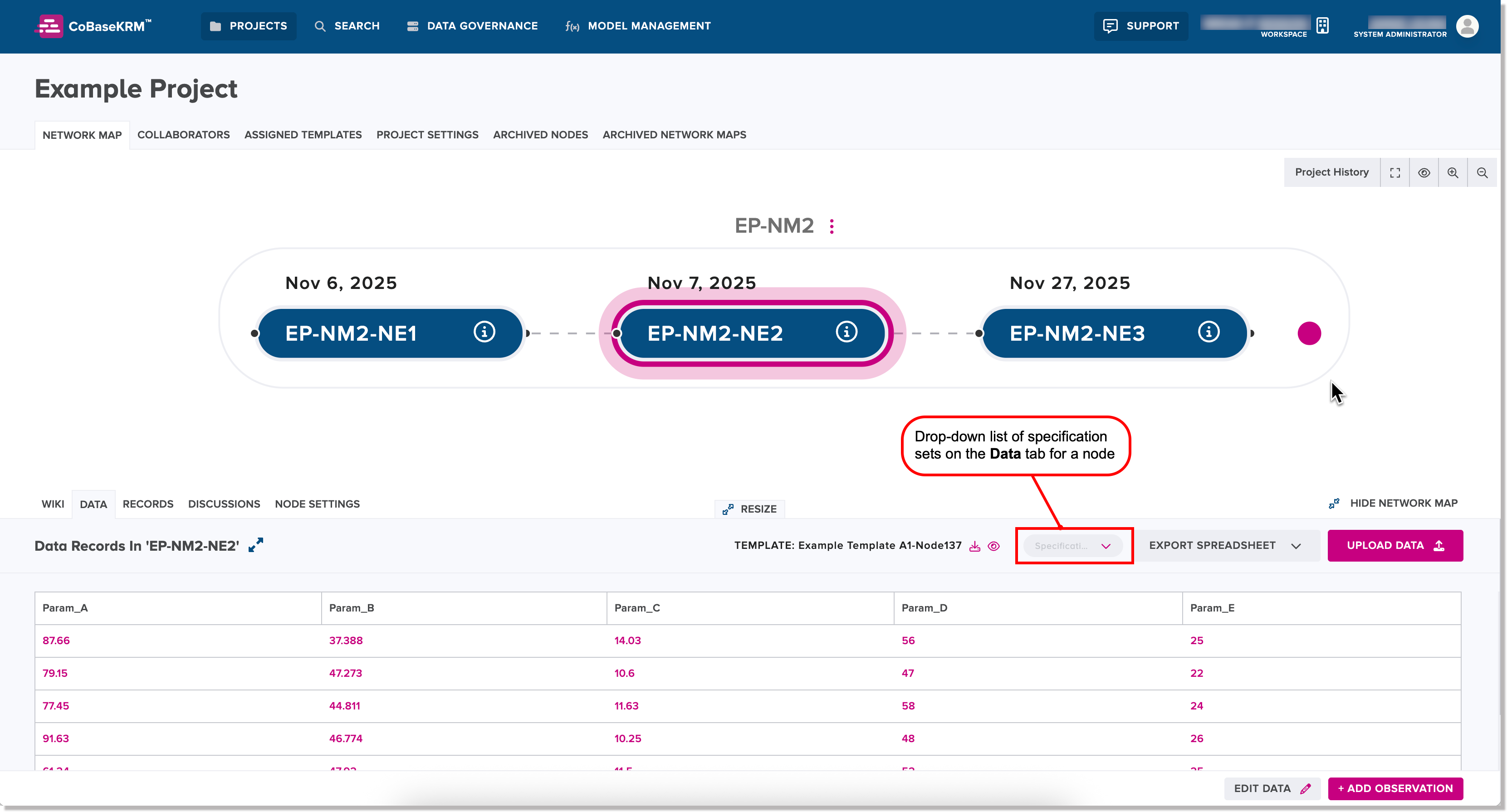
When you select a specification set, the web client visually represents the acceptable range for each parameter having a numeric data type that has a defined specification range as a grey capsule. If a specification range has no defined lower limit, double arrowheads are shown on the left side of the grey capsule. If a specification range has no defined upper limit, double arrowheads are shown to the right of the grey capsule. For example:
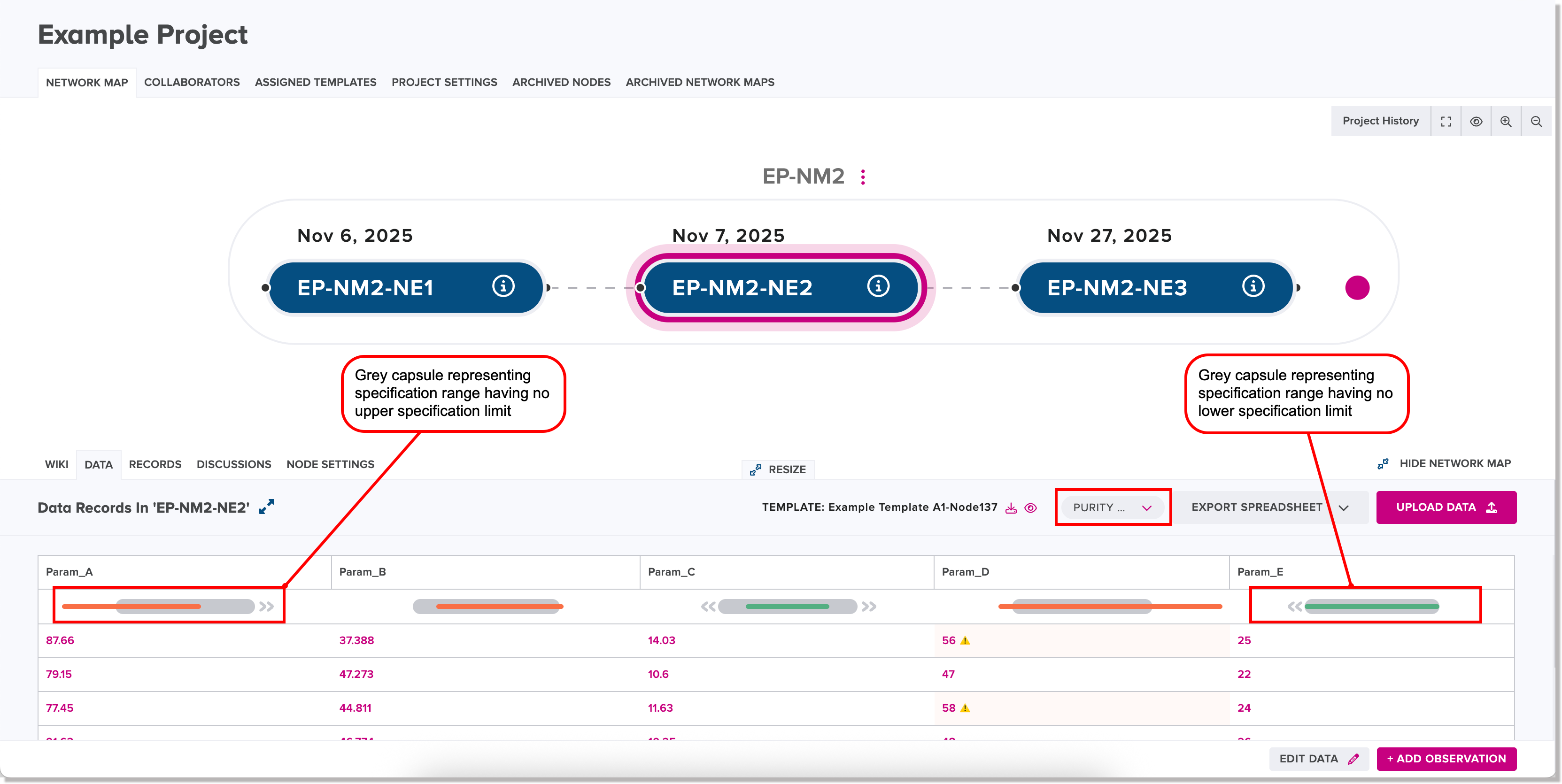
The distribution of observation values for each parameter that has a defined specification range is shown as an orange line that overlays a grey capsule. For example:
When you select multiple specification sets, the web client takes the highest Lower Specification Limit value and the lowest Upper Specification Limit (USL) value and configures a single acceptable range that all of them have in common.
A warning icon is displayed beside any observation values that are outside the selected specifiction range(s).
![]()
To remove a selected specification set from a comparison, click or tap the drop-down list of specification sets and unselect the corresponding specification set name.
Edit parameter values of observations
To edit parameter values of observations related to a node:
-
On the Data tab for a node, click the Edit Data button.
The rows of observations in the data table become editable.
-
Edit parameter values, as needed.
Note
To cancel editing, click or tap Cancel.
-
To save your changes, click or tap Save Spreadsheet.
E-signature collection may be required
If the electronic signature collection feature has been enabled for your workspace, the button will be labeled Sign & Save Spreadsheet. When you click or tap the Sign & Save Spreadsheet button, the Electronic Signature dialog appears.
You are required to fill in the input fields and click or tap Sign & Complete in this dialog to confirm that you are authorized to perform the given action. Once you have input the required details, the system will allow you click or tap Sign & Save Spreadsheet to save the edit.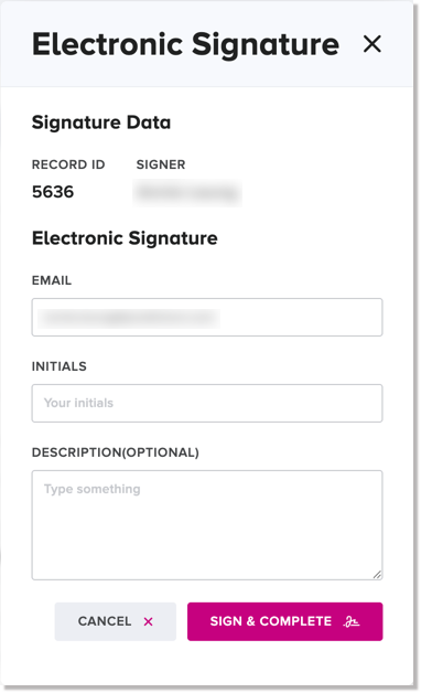
The web client saves the edit and creates a new record accordingly. The view becomes read-only once again.
Add a new observation to a record
To add a new observation to a record:
-
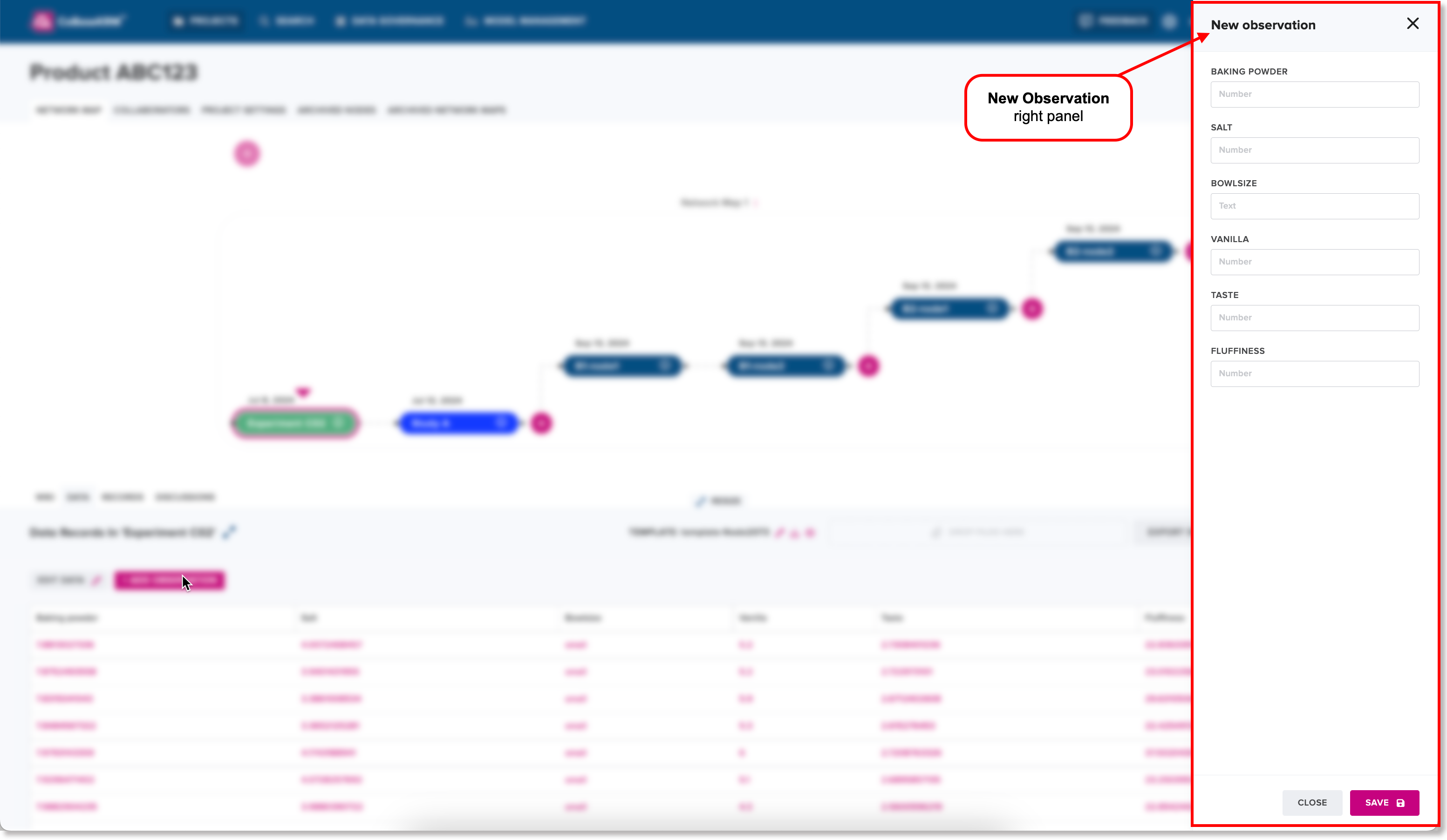
On the Records tab for a node, click or tap the Add Observation button.
A right panel appears to let you input the parameter values of the new observation.
-
In the parameter fields, input values that have a numeric data type.
-
Click or tap Save.
Export a spreadsheet of observations related to a node
To export a spreadsheet of existing observations from the Data tab for a node:
-
Click or tap the Export Spreadsheet button.
A drop-down menu appears, where you can select the file format of the file to be exported.
-
Choose the preferred file format from the menu:
- Excel (.xlsx), or
- comma-separated values (.csv)
The exported file in the selected file format is saved to your local Downloads directory.
Records tab for a node
The Records tab for a node contains in a list of records that indicate historical changes to uploaded observations and supplementary files.
When you hover your cursor over a column heading for a parameter in the data table on the Data tab, a tooltip appears, showing more details and metadata about the parameter.
In the left panel, a record card of the latest version of the modified list of observations is featured at the top of the list. Each record card in the left panel shows the username of the user who uploaded the files for the record, the upload date, a journal card icon for any related journal cards posted, a tag icon representing assigned tags.
When you select a record card in the left panel, its related observations, files, and other details are displayed in the right panel.
Delete an existing record for a node
The web client supports the ability to delete an existing record for a node, which is a permanent action. A deleted record cannot be discoverable through the Search view and cannot be recovered.
To delete an existing record for a node:
-
Navigate to the Records tab for a node.
-
In the list of records in the left panel, select a record card for the record that you want to delete.
-
In the right panel, click the Delete icon for the record that you want to delete.
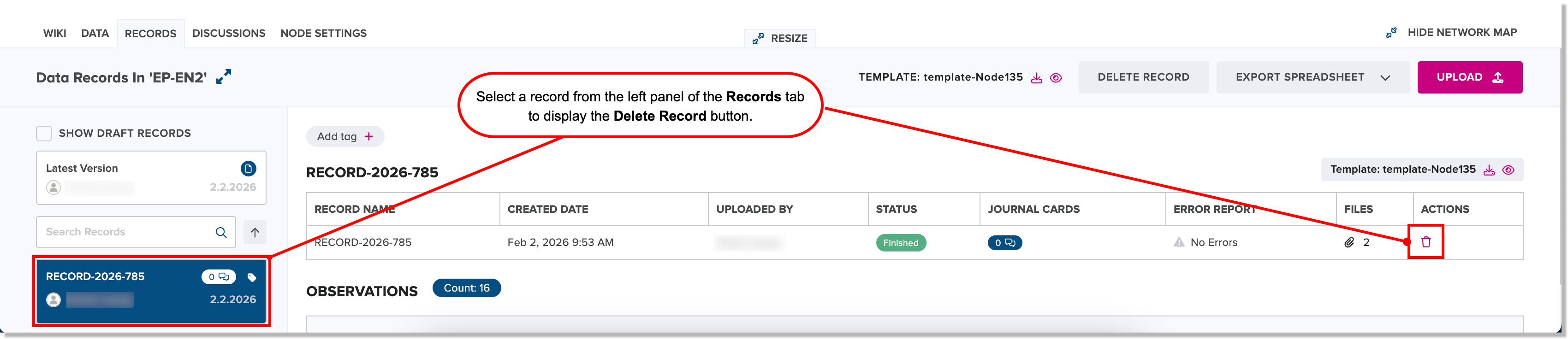
The Delete Record dialog appears.
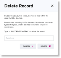
-
In the input field, type the exact record ID to confirm that you want to delete the given record.
-
Click or tap Delete.
The selected record is deleted permanently for the given node, and is removed from being displayed in the left panel of the Records tab.
Delete a file within a record
The web client supports the ability to delete an individual file within a given record for a node.
To delete a file within a record:
-
Navigate to the Records tab for a node.
-
In the list of records in the left panel, select a record card for the record containing a file that you want to delete.
-
In the right panel, scroll vertically until you can view the Files Added in this Record section.
-
Click or tap the Delete icon to the right of the file name to be deleted.
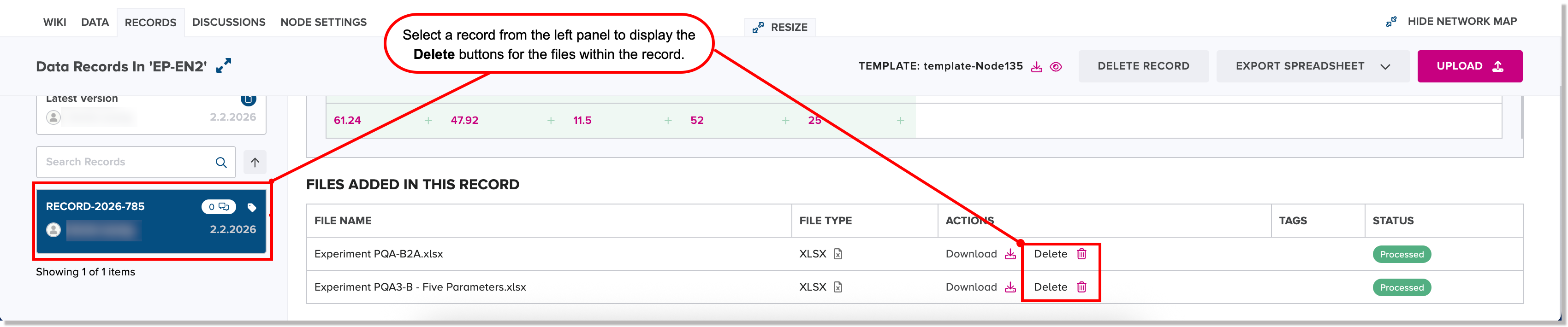
The Delete Record File dialog appears.
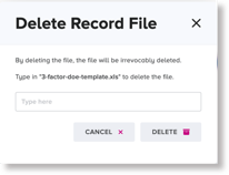
-
In the input field, type the exact file name including the decimal separator and the file extension, and click or tap Delete.
The selected file is deleted permanently for the given node and is removed from being displayed in the Files Added in this Record section of the Records tab.
Discussions tab
The Discussions tab displays the discussion threads of existing journal cards related a node.
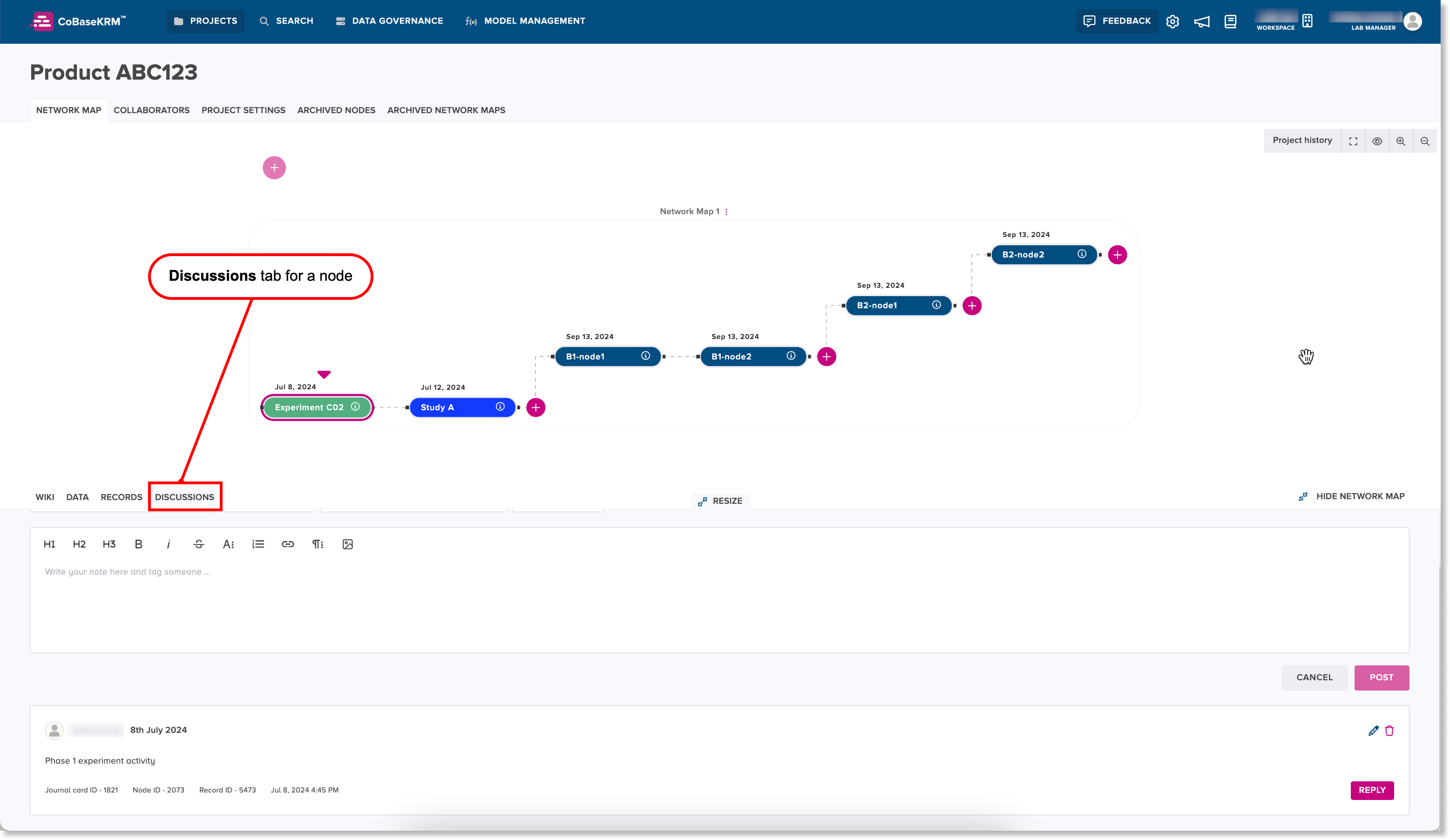
The top section of the Discussions tab features a journal card input field, where you can create a journal card. Common formatting options and heading styles are featured for rich text editing.
Also, you can tag or mention the name of another team member in the journal card input field by first typing the at (@) symbol to display a menu of usernames assigned to the related project, and select a username. Once you have posted the journal card, the web client sends an automatic email notification to the mentioned user. You can also attach images by using the image icon.
Below the journal card input field is a list of existing journal cards. Each journal card displays the username of the user who created the journal card, the created date, comments, mentioned usernames (if applicable), and attached images.
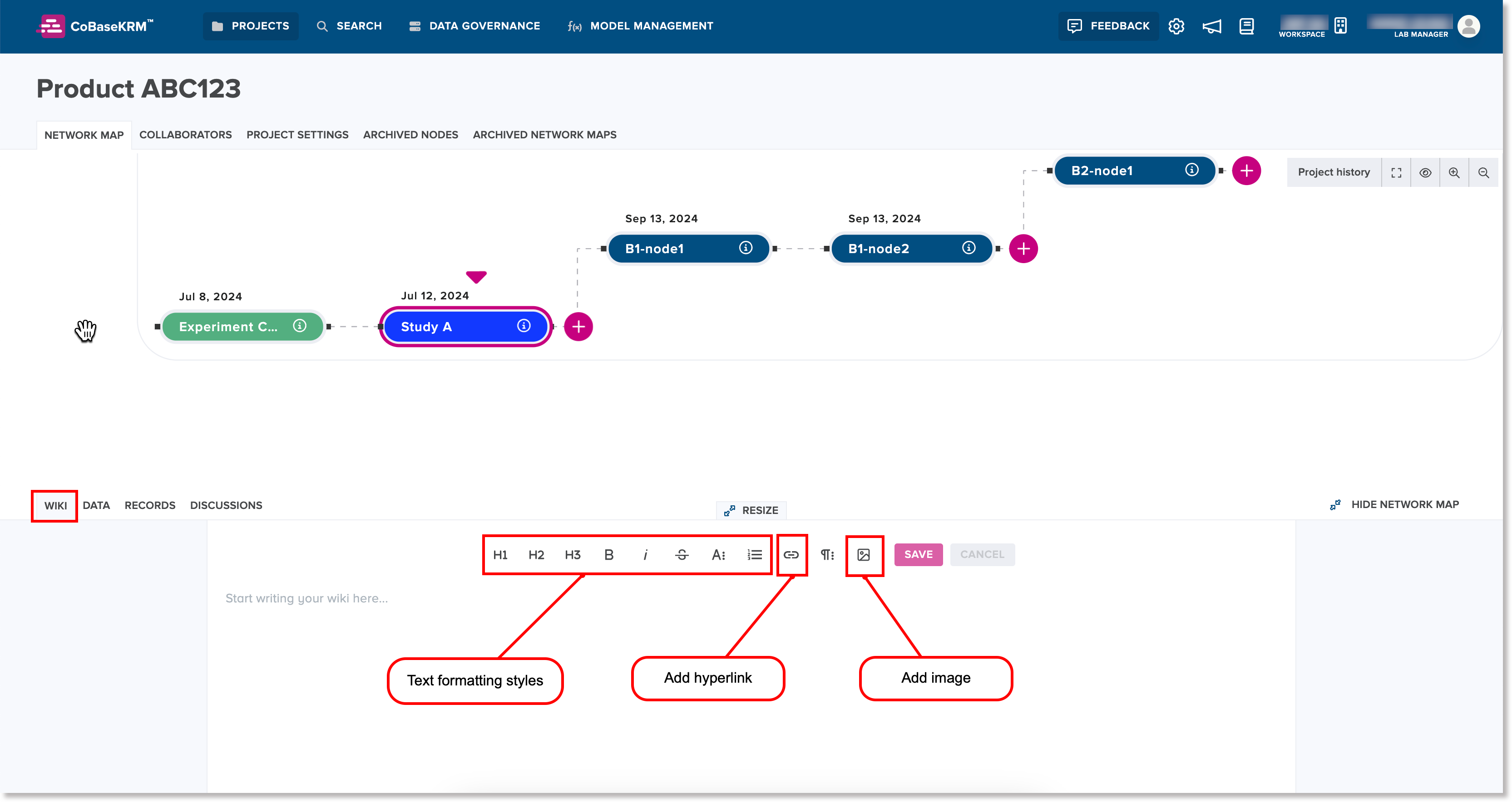
Wiki tab for a node
The Wiki tab for a node lets you create and edit content on a wiki page for a node of a project's network map. The wiki editor features an input field where you can add text and use common heading and text formatting styles. You can also add images and hyperlinks.
To create on the Wiki tab for a node:
-
Place your cursor inside the wiki editor and add text, images, and/or hyperlinks, as needed.
-
Click or tap Save.
Note
If you don't want to save any changes you have made in the wiki editor, click or tap Cancel.
Archive and restore functions
The web client supports the ability to archive network maps and nodes, which become inactive. Also supported is the ability to restore archived network maps and nodes so that they become reactivated.
Note
Because archived network maps and nodes are inactive, their names and IDs are not searchable in the Search view. If archived network maps and nodes are restored and become reactivated, their names and IDs become searchable once again.
More details about the archive and restore functions are outlined in the corresponding sections below.
Because nodes are connected by existing data object relationships, when a node is archived or restored, the web client will update affected relationships accordingly, as described in the corresponding sections below.
Archive a network map
When you archive a network map, all of its dependent objects also become archived and inactive. Therefore, details of an archived network map and its dependent objects will not be searchable in the Search view.
To archive a network map:
- In the Network Map tab for a project, click the menu icon to the right of the name of the network map that you want to archive, and select the Archive network map option.
![]()
The Archive network map dialog appears, informing you of the resulting behavior if you proceed with the action.
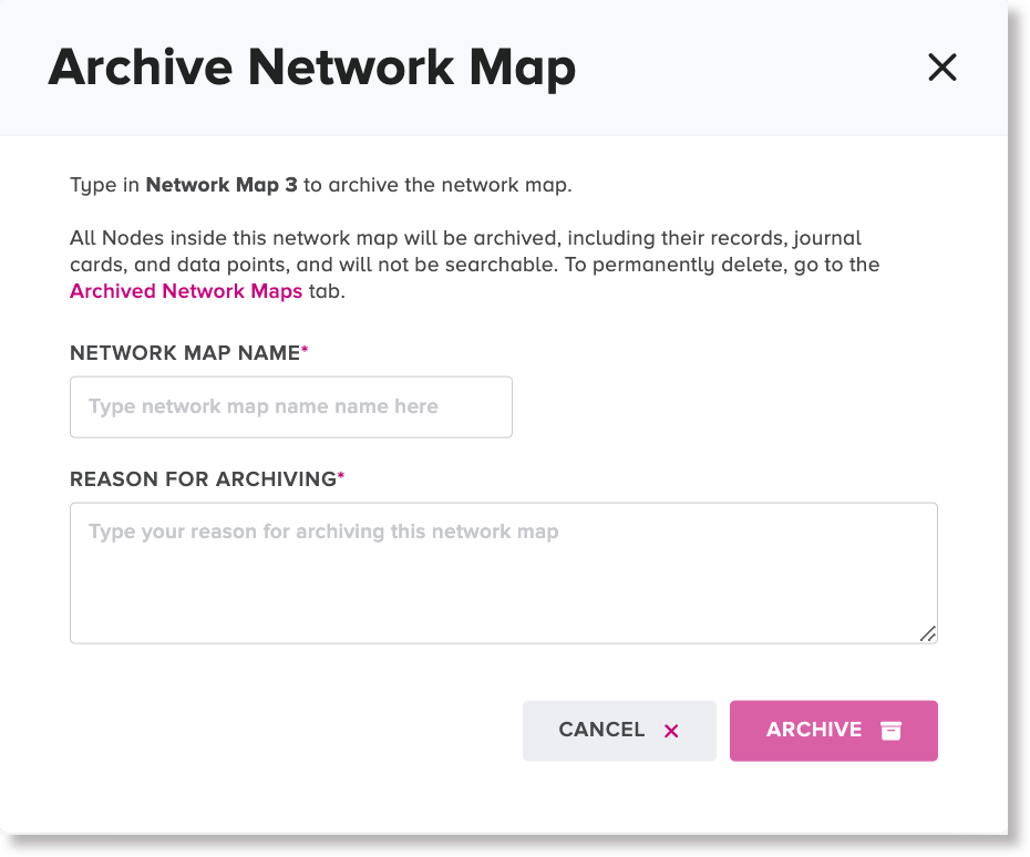
- To cancel the archive action, click or tap **Cancel**.
- To proceed with archiving the given network map, click or tap **Archive**.
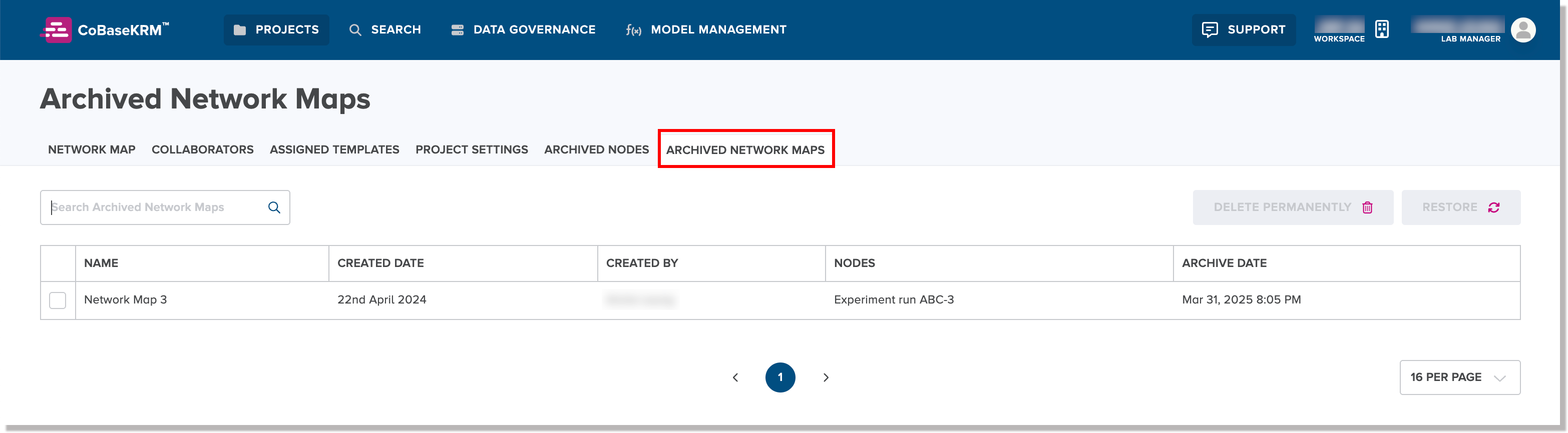
The web client removes the network map from the **Network Map** tab of the project. The network map name becomes listed on the **Archived Network Maps** tab for the project. In the listing, the name of the archived network map, created date, username of the user who created the network map, related node names, and archive date are also displayed.
Archive a node
When you archive a node, it and all of its dependent objects will be removed from the related network map of a project, will become inactive, and will not be searchable in the Search view.
To archive a node:
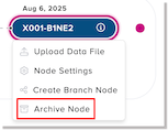
- On the Network Map tab of a project, right-click on a node that you want to archive and from the menu, select Archive node.
The Archive node dialog appears.
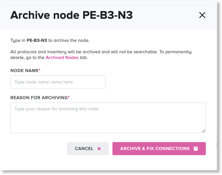
-
In the input field, which is case sensitive, type the exact name of the node.
-
In the Reason field, type a reason for archiving the node.
-
Click or tap Archive.
The node is removed from the given network map and becomes listed with its archive date on the Archived Nodes tab for the related network map.

The node has become an inactive object and is undiscoverable in the Search view. A direct node relationship is created between the preceding node and successive node where the archived node was formerly positioned in the related network map.
Restore an archived network map
When you restore a network map to a project, all of its dependent objects will also become restored as active objects. The restored network map becomes searchable once again in the Search view.
To restore a network map:
-
On the Archived Network Maps tab for a project, select the checkbox to the left of the name of the archived network map to be restored.
-
Click or tap the Restore button.
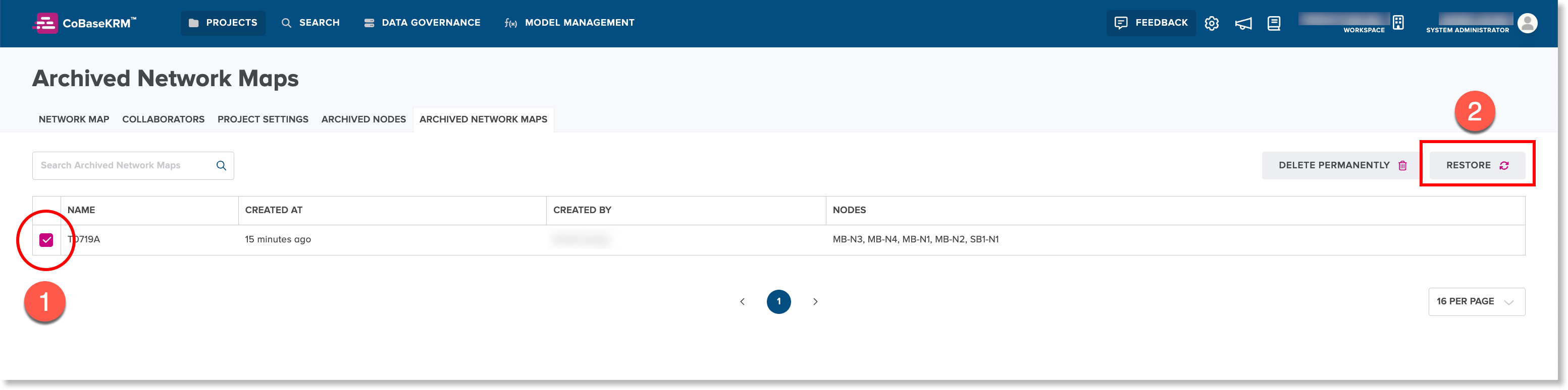
The name of the network map is removed from the Archived network maps tab. The network map is restored to be displayed on the Network maps tag for the given project.
Restore an archived node
When you restore an archived node, all of its dependent objects will also become restored as active objects. You have the option of reconnecting the restored node to its former preceding node and successive node, if desired, or connect the restored node to different nodes.
To restore an archived node:
- On the Archived Nodes tab for a project, select the checkbox beside the name of the archived node to be restored.
The Node Restoration Check Connections dialog appears. The web client checks the node's history to determine the former node relationships that were in place before the node was archived, and presents the node relationships accordingly.
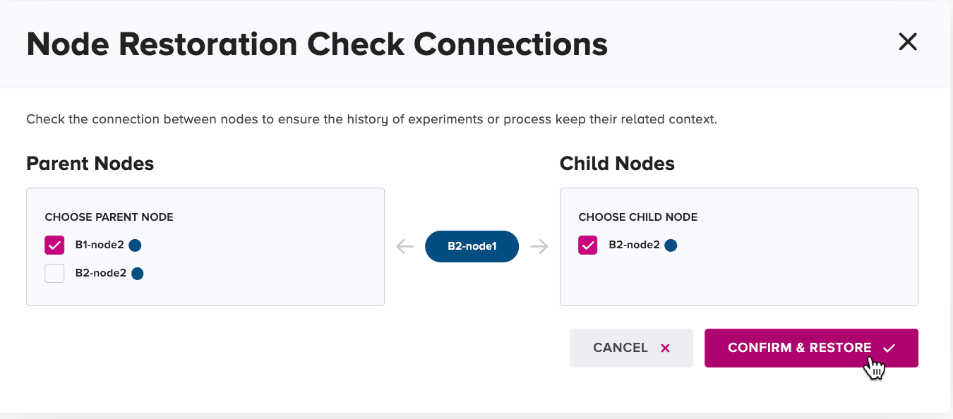
If the archived node was not related to a preceding node, no node name is presented in the "Parent node" section. If the archived node was not related to a successive node, no node name is presented in the "Child node" section.
-
If applicable, in the Parent Node section, select the checkbox for the node that had been the preceding node before the given node was archived.
-
If applicable, on the Child Node section, select the checkbox for the node that had been the successor node before the given node was archived.
-
Click or tap the Restore * confirm button.
The archived node is removed from the Archived nodes tab, and is displayed in its former position and branch on the Network Maps tab of the given project.